IBA KOREA SYSTEM
IBA - 데이터 분석시스템
다양한 어플리케이션과 요구에 맞게 설계합니다.
IBA는 측정된 데이터에 대한 수집, 기록, 분석, 재해석 등 에 필요한 하드웨어 및 소프트웨어로 구성된 데이터 수집 장치 및 분석 툴입니다.

모듈화된 설계와 간단한 시스템 구성 덕분에 IBA 시스템은 어떤 규모의 데이터 수집은 물론 다양한 어플리케이션과 요구에 맞게끔 시스템을
설계, 구성하여 사용할수 있습니다. 이러한 컨셉을 통해 64채널의 간단한 포터블 수집장치로부터 수천개의 데이터를 한꺼번에 수집할 수 있는
서버까지 구축하실 수 있습니다. 또한 한 번 설치 이후, 요구에 따라 손쉽게 기존 시스템을 업그레이드 하실 수 있습니다.

Time synchronization - ibaClock

본문

Time synchronization for distributed systems

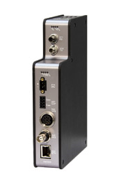
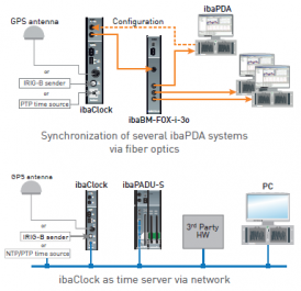
With the time synchronization module ibaClock, several distributed iba systems can be synchronized precisely. ibaClock provides a precise time basis for all connected systems and enables an exact synchronized data acquisition.

b5648be4a8231f524e928cd1320ec08d_1554973


At a glance

 ·         High precision time server

 ·         Time sources: GPS signal, IRIG-B or IEEE 1588

 ·         Fiber optic connection to ibaPDA systems via ibaFOB-D cards

 ·         Synchronization of ibaPDA systems with sample accuracy

 ·         Can be used as IEEE 1588 time server or as NTP time server in a network

 ·         Configuration and diagnostics via ibaPDA or web interface

 ·         Completely maintenance-free

 ·         Rugged design, easy mounting


Highest precision

The timebase for ibaPDA systems is the clock of the respective ibaPDA computer. In case decentrally acquired data have to be correlated or a measurement has to be done in real time, it is necessary in such distributed systems to synchronize all computers or provide the exact GPS time to a computer.

ibaClock determines a uniform, exact time basis for all connected systems and enables an exact time synchronous recording of the data with a precision of better than 150 ns. The measurement systems are connected to ibaClock using fiber optic cables.

ibaClock can use different time sources:

 ·         GPS time signal

 ·         Timecode IRIG-B

 ·         Ethernet-based PTP (Precision Time Protocol) according to IEEE 1588 standard

For synchronizing the time of non-iba systems, ibaClock supports several time server models:

 ·         Fiber optics for ibaPDA systems

 ·         IEEE 1588 (PTP)

 ·         NTP

 ·         DCF77*

*for future fi rmware versions.


Configuration in ibaPDA or Web Interface

ibaClock can be confi gured using ibaPDA or a web interface. The user can see the quality of the GPS signal and the device status on the LED display of the device or in the web interface and ibaPDA.


Antenna

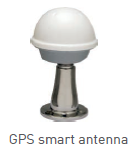
The device supports a special GPS smart antenna, that can be mounted with a cable length of up to 400 m from the device. The antenna with a suitable cable and an optional mounting bracket can be purchased from iba.


b5648be4a8231f524e928cd1320ec08d_1554973 

Fields of application

 ·         Correlation of decentrally acquired data

 ·         Linking processes in decentralized structures

 ·         Energy supply (phasor measurement)


b5648be4a8231f524e928cd1320ec08d_1554973

 Name

 ibaClock

 Description

 Universal time server

 Order number

 10.160000

 Time sources

 GPS

 Supported GPS antenna: Smart antenna Trimble Acutime GG/Acutime 360,
 power supply via ibaClock
 Antenna precision: 15 ns (static)
 Cable length: up to 400 m
 Control accuracy of internal PLL: (typ.) < ±150 ns of the absolute GPS-PPS signal
 Time stability in case of GPS signal loss: < 0.15 ppm after at least 10 minutes GPS
 reception

 IRIG-B

 Plug connector: BNC, 50 Ω
 Supported telegrams: B004, B124, B005, B125, B006, B126, B007, B127
 IEEE1344 / IEEE C37.118
 AFNOR NF S87-500

 IEEE 1588

 PTP (Precision Time Protocol), hardware based

 Time server function

 ibaNet

 Time synchronization of ibaPDA systems via fiber optics

 IEEE 1588

 PTP (Precision Time Protocol), hardware based

 NTP Time & Daytime

 Synchronization over network via NTP
 According to RFC 868 and RFC 867

 DCF77

 Optionally: output of DCF77 time code via semiconductor relay output

 Alarm

 Alarm

 Semiconductor relay output , switching current up to 200 mA, open in de-energized state

 Interfaces/features

 Fiber optics

 Time synchronization, configuration and diagnostics

 Ethernet

 RJ45 socket (Ethernet 10/100 Mbit/s) for configuration and diagnostics

 Simulation

 Time server function without active time source (e. g. commissioning, etc.)

 Freewheel accuracy

 High-precision with PLL-controlled internal quartz basis

 RTC

 Buffered RTC (Real Time Clock) for approx. 10 days

 Supply and indicators

 Power supply

 24 V DC (±10 %), unstabilized

 Power consumption

 Up to 2 W (without antenna), approx. 2.5 W (with antenna)

 Indicators

 4 LEDs for operating status of the device
 4 LEDs for status of the time sources

 Operating and environmental conditions

 Cooling

 Passive

 Operating temperature

 32 °F to 122 °F (0 °C to 50 °C)

 Storage / transport 

 temperature

 -13 °F to 149 °F (-25 °C to 65°C)

 Humidity class (DIN 40040)

 F, no condensation

 Protection class

 IP20

 Certification

 EMC: EN 55011:2009+A1:2010, EN 61326-1:2013, FCC part 15 class A

 Mounting

 DIN rail, vertical

 Dimensions and weight

 Dimensions (w x h x d)

 1.5 in x 7.4 in x 5.7 in (37 mm x 188 mm x 145 mm), incl. DIN rail clip

 Weight (incl. packaging

 and documentation)

 Approx. 1.1 kg